


|
|
| The physically based simulation of all light distribution in a virtual 3D-model is called global illumination. A global illumination algorithm should take into account all interactions of light with the different surface materials in a scene. That sounds alright in theory, but the nature of light - having both the properties of a electromagnetic wave and a particle, is much to complex to include all phenomena in a correct physical simulation. Anyway, what counts is only the individual perception of light, since we can only "see" a limited spectrum of light and the interpretation of what we see is a mainly physiological sensation.
|
|
|
| The global illumination algorithm implemented in CyberMotion is based on a combination of photon mapping with conventional raytracing. So, let's have a look at the raytracing algorithm first.
|
|
|
|
|
|
| In nature, a light-ray that leaves a light-source, reflects off different objects and then falls, sometime later, into the eye. Raytracing is exactly the reverse process. A "viewing ray" is sent out from the camera-viewpoint, through a projection-plane (the screen) and then tested for an intersection with an object in the area. If an intersection occurs the relevant pixel of the screen - at the point where the viewing ray passes through the projection-plane - can, therefore, be drawn in the calculated surface-intensity of the object. The viewing ray can also be followed further, however. At a mirroring object the angle of reflections is simply calculated and a new ray started searching. The surface intensity for the first object met then comes recursively from the incident light in addition to the light reflected from the other objects that are met.
|
| With this algorithm it is also possible to calculate the split in the viewing rays that is necessary with transparency. In order to render transparency realistically the surface-reflections are calculated from reflections in addition to the intensity of the light coming from behind. A mirror-ray and simultaneously a split viewing ray is calculated. If these viewing rays meet another transparent or mirror object, the whole process is started again, so the color for rendering only a single screen-point results from a whole collection of viewing rays.
|
|
|
| Direct and Indirect Illumination
|
| Raytracing is a standard for high picture quality and for realistic reflections and refraction. One of the major drawbacks in a general raytracing implementation is that it does not take into account the indirect illumination - the light that is reflected from other objects in the scene other than the direct light from a light source.
|
|
| Direct light is coming in directly from the light source, indirect light is reflected at least once from a surface in the scene.
|
|
|

|
| Direct light and surface brightness - In a conventional illumination model the light intensity coming directly from the light source is determined by calculating the light incidence angle between the light ray and the surface normal. This is of course only a geometrical approach, but it has produced good results for years in the computer graphics industry.
|
|
|
| Raytracing and Indirect Illumination
|
| Usually in 3D programs a constant light intensity can be specified to simulate the indirect illumination in non global illumination models. In CyberMotion this constant general area brightness is defined with the light object "Ambient". Another possibility to simulate indirect light is to put additional lights with a lower intensity level directly opposed to the main lights emission direction. This will help to lighten up deep shadows cast by the main light source. All in all, both methods are very poor approximations. Escpecially in architectural scenes the illumination in a room is dominated by indirect light reflected many times from the diffuse sufaces in a building.
|
|
|
|
|
| Now, with the newly implemented photon mapping algorithm, CyberMotion provides a global illumination model that combines the pros of raytracing - reflection and refraction - with the ability to render also the indirect illumination caused by diffuse reflections in the scene. Rendering a picture with photon mapping is a two pass procedure. In a preliminary run little packages of energy (photons) are emitted from the light objects in the scene. Similar to ordinary raytracing the path of this photons is traced through the scene and just like in raytracing photons are reflected from specular surfaces and transmitted through transparent objects.
|
|
| Photon scattering is a more realistic simulation of light because it comes closer to the natural distribution of light from its source.
|
|
|
| Each time a photon hits a diffuse surface, the position and properties of the photon are stored in a 3-dimensional data structure called the photon map. Simultaneously a diffuse reflection is calculated and the diffuse reflected photon continues its way through the scene until it is absorbed in the scene or lost in space. Depending on the render options, scene data and light settings a photon map can rapidly blow up to several millions of photons stored in it. Therefore, be sure to have enough RAM memory available (128mb minimum), before entering astronomical numbers of photons for the light emission parameters.
|
|
|
| After the photon map has been build during the first pass of the rendering process, an ordinary raytracing pass is started and the light data stored in the photon map can be evaluated to estimate the light incidence for a point on a surface. For a good estimation of the incoming irradiance a specific number of photons scattered around that point have to be gathered in the so called photon pool. The maximum number of photons to search for the photon pool determines the quality, sharpness and of course the rendering time. You should take into account that searching through a photon map that might hold millions of photon entries is not really a trivial thing. The size of the photon pool can be entered in the render options dialog.
|
| Appropriate values for the photon pool size lie between 250 and 800 photons when photon mapping is applied only for the indirect lighting, and 500 up to 5000 photons, when Global Illumination mode is activated with photon maps containing several million photons. As a rule you can say, the more photons in the photon map the more photons should be gathered in the photon pool, otherwise the pictures become a somewhat spotty appearance.
|
|
|
| In CyberMotion you can choose whether you want to apply photon mapping only for determining the indirect illumination in a scene or as a global illumination model for all of the light distribution in the scene: You can change between these two modes in the render options dialog.
|
|
|
| With this option the photon map is only evaluated to estimate the indirect illumination caused by diffuse reflections in the scene. The main part of the illumination and shadow calculations will be rendered with help of the directly incoming light, taking into account the light incidence angle between the light ray coming from the light source and the surface normal vector, as it was described in the beginning of this chapter.
|
| Advantage: When applying a photon map only for indirect illumination then you can manage with relative small photon maps. To estimate the general area brightness in a small room you can do with photon maps of 50,000 photons and upwards. To soften the sharp shadows calculated from the direct lighting you can use multiple shadow sensors or insert area light objects. In general, shadows calculated from direct lighting are more accurate than shadows generated from a pure photon map - when photon mapping is applied as a global illumination model. If not enough photons are emitted towards the scene, contours of the shadows become to blurry and smaller shapes in the scene may not be hit at all.
|
| Disadvantage: The combination of the different illumination models requires an adjustment of the light intensities - on the one hand the intensity evaluated from the photon map and on the other hand the irradiance calculated from the vector pointing directly towards the light source. In the light dialog you can adjust the photon intensities via the "Intensity Correction " parameter. Once an appropriate correction value has been found, you can simply adjust light intensities as usual and switch to and fro form normal raytracing to photon mapping without further adjustments to the correction parameters.
|
|
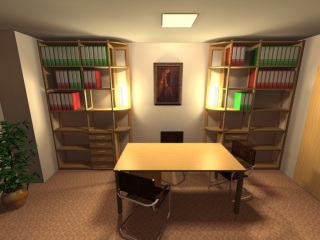
| This example was rendered with photon mapping only for the indirect illumination. An area light object (NURBS patch with 49 shadow sensors) at the ceiling and 2 table lamps (36 shadow sensors each) standing in the shelves provide a warm lighting and soft shadows. For the photon mapping process the ceiling lamp emits 100,000 photons and the two table lamps 50,000 each. The effect is a soft area brightness illuminating the otherwise dark areas beneath the table and in the shelves. You can download this project file from our internet library if you like.
|
| .
|

|
| Another example (the project file for this example is part of the installation under "../projects/volumetricfire/candles_anim.cmo"). Two candles and a third light source behind the camera are emitting 50,000 photons each for the indirect illumination. Because of the reasonably small photon map a corresponding small number of only 350 photons can be entered for the photon pool size. To soften the shadows casted by the direct lighting again multiple shadow sensors were applied for each light source. If you would try to render the same picture with photon mapping as a global illumination model, then much more photons had to be emitted by the candles, otherwise the relative thin candle shadows would not be visible at all. This is totally independent of the complexity of the scene. To get clearly visible shadows from the thin candles certainly about a million photons were necessary for each light source. With it, you would have to enter a corresponding high number of photons to gather for the photon pool to get smooth intensity transitions and to prevent a spotty appearance.
|
|
|
|
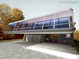
| Example of an architectural outdoor scene and photon mapping only for indirect illumination (model: John Ridgway, Julia's House from the "Frontiers"-comic book series - you can download the project file from the internet library). This time a parallel sun light was applied (emitting 1 million photons, photon pool size of 1000 and 36 shadow sensors scanning the sun disc).
|
| When rendering outdoor scenes with parallel lights, you should note that all photons emitted by the parallel light source are directed towards a bounding box surrounding all objects in the scene. Of course, the plane object will be ignored when calculating the dimensions of the bounding box - we certainly do not want to scatter around millions of photons on an infinite plane. This is why the illumination of plane objects will always be carried out with direct lighting, no matter which rendering mode you select (see also: Material Dialog - Object Properties - Only Direct Light). To maintain the diffuse light interactions between ground floor and buildings you should create an additional base plate that is placed slightly above the plane and is adjusted to the dimensions of the scene. In the example depicted above this was realized with the grassy subsoil plate beneath the asphalt ground.
|
|
|
| If you choose <Global Illumination> in the render options dialog, then all light interactions in the scene will be calculated by evaluating the photon map only.
|
| Advantage - The whole illumination is made in one casting, there is no need to combine and coordinate the different lighting models. Also, the calculation of shadow sensors can be omitted, since all light scattering is provided by the photon map and shadows will result automatically from the distribution of photons in the scene. Because of the averaging of intensities about many photons shadows become very soft and the whole scene gets a very natural atmosphere.
|
| Disadvantage - As described earlier in this chapter the shadows often become to soft, especially when emitting too few photons. To get accurate illuminations of minor details in the scene you have to emit a great number of photons, usually a million and more. Furthermore, you have to enter a corresponding high number of photons to gather for the photon pool to get smooth intensity transitions and to prevent a spotty appearance (about 600 up to 2500 and more, depending on the size of the photon map). This requires a fast cpu and a high memory capacity of at least 256mb and more. Before rendering pictures demanding so much computer power and time you should always render preview pictures with a lower resolution of emitted photons and a smaller number of photons to gather in the photon pool. The light intensities are distributed consistently among the whole of all emitted photons, so that the picture brightness is constant and independently of the number of photons emitted. Therefore, you can render good test images using photon resolutions of 50,000 up to 100,000 photons for the emission and photon pools with 250 up to 500 photons for the evaluation of the photon map. Only when you adjusted scene settings, render options and light intensities the final rendering can be started with lights emitting millions of photons and a photon pool picking up about 600 to 5000 photons for each shading of a point on a surface.
|
|
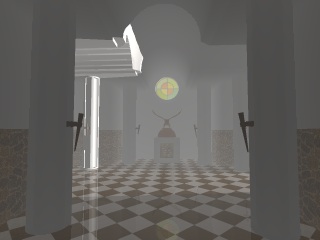
| Example: This picture of a great hall was rendered in global illumination mode. The only light source is a spotlight placed in front of a side entrance and thus simulating sun light penetrating through an open door. The spotlight shoots about 2 million photons through the side entrance into the hall. For the evaluation of the photon map the photon pool size was limited to 700 photons. Initially all photons are directed along the side corridor, but you can clearly see that actual all parts of the hall are illuminated, even at the end of the main corridor where the camera is positioned. This is due to the manifold diffuse reflections the photons have carried out tracing their way through the architecture. The picture was rendered on a P4, 2.54GHz with 256mb RAM in a resolution of 800 * 600 pixels and antialiasing switched on in only 13 minutes. That's quite respectable I think (as compared with other implementations rendering whole days for some boxes or spheres in a bare room).
|
|
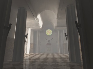
| This pictures shows the same scene when rendered without photon mapping - just pure raytracing and direct illumination. Because there is no diffuse interaction of light in the scene only the side corridor is illuminated. Nevertheless, you can discern the columns in the main corridor, but that's only because the fog function has been switched on, so that the shapes get brighter with distance and fog density. Of course you could also switch on the constant ambient light, but columns, walls and ceiling are designed in one basic color, so increasing the light intensity with a constant term would not add to the visible detail. In such a case, if you really want to evade using photon mapping, you would have to place some low intensity lights at the corridor ends to simulate the light reflected from the walls.
|
|
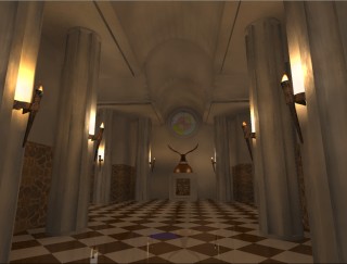
| Once again the hall rendered in global illumination mode, this time illuminated by 16 burning torches creating a dim atmosphere in the hall. Although using much more light objects in this example, the rendering time is not much higher than in our first example of the daylight scene with only one spotlight in front of the side door. This is due to the fact, that only the whole amount of emitted photons and with it the size of the final photon map counts for the rendering time. In the example depicted above only 60,000 photons were emitted for each torch light, adding up to only 960,000 photons. That's just half of the photon number the single spotlight emitted in the day light example.
|
|
|
|
|

|
| Photon mapping is ideal for rendering landscapes too. The diffuse reflected photons in the terrain create subtly graded tones even in areas that lie in the deepest shadows. The picture above was rendered in global illumination mode and one million photons emitted by the sun light. Because no additional shadow calculations are involved (in contrast to direct lighting) the rendering time added up to only 30 minutes (compared to 11 minutes in raytracing mode with shadows). The picture rendered on P4, 2.54GHz, 256mb RAM, picture resolution 800 * 500 pixels, with antialiasing and a terrain resolution of 700,000 facets. In contrast to architectural scenes the photon pool can also be limited to small numbers of photons to gather (400 photons in the example). When gathering too few photons for the irradiance estimation than plain surfaces appear spotty and disturbing, especially in architectural scenes, but in terrains with high detailed landscape textures this effect is barely discernible.
|
|
|
|
|
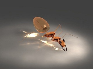
| The examples discussed beforehand present mainly the advantages of photon mapping regarding the diffuse interactions of light - when light is reflected randomly from rough surfaces. But with photon mapping you can also trace the path of photons that are reflected from highly specular surfaces or transmit through transparent materials. The visible light patterns arising from these reflections are so-called caustics.
|
|
| Example for caustic light reflections beneath a little glass figurine, caused by photons that were refracted when transmitting through the glass. The project file is part of the CyberMotion installation under "/projects/caustics/ant.cmo".
|
|
|
| Caustics Photons are stored in a separate Photon Map, the so-called Caustics Map:
|
| Usually a photon map is evaluated only for the indirect illumination in combination with direct light for the main illumination and shadow calculations. For this purpose it will do to emit only several ten thousands of photons into the scene so we can average the general area brightness at each point in the scene. Caustic reflections, on the other hand, are often sharp outlined light patterns, like in our figurine picture shown above. It would be impossible to render these light reflections when only a few photons had been scattered around - you wouldn't even see a glimpse of the light focused beneath the figurine. Now, it would be also ridiculous to emit millions of photons into the scene and having to evaluate huge photon maps afterwards, only to cover the light reflections of a little specular object somewhere in the scene. That's why we have to manage to different photon maps, one for the global photon map and the general illumination, and one separate caustic map only for those photons that have been reflected or transmitted via a specular surface before hitting a diffuse surface. The caustic map is build in a second photon tracing pass where additional caustic photons are aimed only towards such objects, that are highly specular or transparent and own the material attribute <Caustics - Aim Additional Photons at Object>. The evaluation of the two different photon maps requires also separate photon pools. For the global photon pool much more photons have to be gathered for the averaging process, so that soft and clean light transitions can be calculated for the area brightness. However, for the caustics pool we need comparatively fewer photons, because we want sharp and clearly visible light reflections.
|
| You can adjust the size of the caustic pool in the render options dialog, as with the global photon pool. The emission of additional caustic photons can be switched on or off for each light object separately in the light dialog. You should activate the caustic photon emission only for lights that stand nearby or are directed towards objects, that own the object attribute <Caustics - Aim Additional Photons at Object>. If you want to render a picture with the camera focused on a caustics object as the main part of the image, it is advisable to use a spot lamp for the illumination because then the stream of photons can be aimed directly towards the target object.
|
| The number of additional caustic photons emitted from a light source is entered via the light emission parameters in the light dialog. Instead of specifying a certain number of photons this time you just have to enter a factor that describes how much more photons per area have to be emitted towards the caustic objects than for the global photons. Take again the glass figurine as an example. The emission of global photons was set to 50,000 photons. For the emission of caustic photons the factor was set to the maximum value of 100 via the <n-Times more Photons>-Parameter. During the processing of the photon map in the first pass, when the 50,000 global photons are emitted, about 1100 photons found their way through the glass figure and were saved in the caustic map. Then the additional emission of caustic photons is started with 100-times more photons, this is 100 * 50,000 = 5 millions photons. But this is only a fictitious value that only specifies how much more photons per area are emitted in general. Since caustic photons are only directed towards caustic objects in the end "only" 200,000 photons find their way into the caustics map. This is more than enough for a sharp representation of the caustic light effects under the glass figure.
|
|
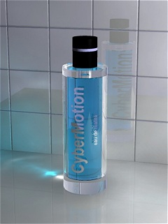
| This picture was rendered under the same conditions in global illumination mode. Only 100,000 photons are emitted from a simple point light source and a factor of 100 for the additional caustic photons. As a reward wonderful light reflections show on the wall and the basis. This demo is found in the projects folder of the CyberMotion installation under "/projects/caustics/perfum_photonmap.cmo".
|
|
|
|
|
|
|
| Deactivating Photon Mapping for Individual Light Sources
|
| Each light source in CyberMotion can emit photons for the photon mapping process. However, you can also exclude individual light objects from this process. If you switch on the <No Photon Mapping for this Light Object> option in the light dialog, then, instead of emitting photons, the corresponding light object will illuminate the scene only with conventional direct light algorithms, no matter which rendering mode is activated. You can use this function for little lamps in instrument controls or for lights far away in the background or, e.g., for spot lamps illuminating only small parts of the scene. To save rendering time just switch on this function for all light objects that do not contribute much to the general illumination in the scene.
|
|
|
| Deactivating Photon Mapping for Individual Objects
|
| You can exclude individual objects from the photon mapping process too. If you switch on the object attribute <Only Direct Light - No Photon Mapping> in the material dialog, then the object becomes invisible for photons and is illuminated directly instead by each light source. Possible uses:
|
| · | if rendering in global illumination mode (only photon mapping, no direct lighting) and a small object is not hit by enough photons to shade it accurately. Instead of emitting more photons you can exclude these small objects from photon mapping and they will be correctly shaded again with direct lighting.
|
| · | if rendering moving objects in an animation with a static photon map. If the photon map is calculated only once at the start of the animation then objects excluded from photon mapping can still move through the scene.
|
| For the plane object this attribute is switched on automatically. Since the plane extends up to the horizon it would be nonsens to waste photons above this infinite plane.
|
|
|
| Static Photon Map in Animation
|
| If you activate this feature in the render options dialog, the photon map will be calculated only once at the beginning of an animation. You can use this option to animate a fly through an architectural scene where the objects themselves do not move. It is also possible to exclude individual objects from the photon mapping process - those will be illuminated only with direct lighting - and then you can even render animations with a static photon map and moving objects, e.g. a car driving through a street lined with houses.
|